|
|
|
(Note: These tutorials are meant to provide
illustrative examples of how to use the AMBER software suite to carry out
simulations that can be run on a simple workstation in a reasonable period of
time. They do not necessarily provide the optimal choice of parameters or
methods for the particular application area.)
Copyright Ross Walker 2006
AMBER ADVANCED WORKSHOP
TUTORIAL A5 - SECTION 2
The Nudged Elastic Band Approach to Finding the Lowest
Energy
Pathway Between two States
By Ross Walker
2. Constructing the Pathway End Points
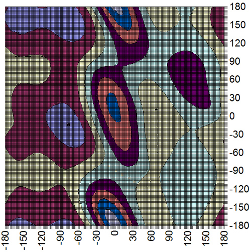
Each amino acid in a peptide or protein has two degrees of backbone freedom. The angle denoted phi describes rotation about the C(alpha)-N bond of the amino acid, and the angle psi denotes rotation about the bond linking the alpha carbon and the carbonyl carbon.
In this tutorial we will attempt to find the lowest pathway on the potential energy surface shown on the index page for the rotation of alanine dipeptide between the following two structures. Note: this problem is a fairly trivial example since the potential energy surface is two dimensional and it is fairly easy, by scanning, to calculate the entire surface. However, in a real example the surface would be multidimensional and so plotting the pathway as we are doing here would not be possible. This alanine example thus serves as a test to show that we are indeed finding the shortest pathway.
Note: In this example the dynamics are represented by the classical force field equation and so the NEB method here is limited to studying a conformational change. However, Amber 9 supports QM/MM NEB as well which allows reaction pathways to be studied.
|
|
|
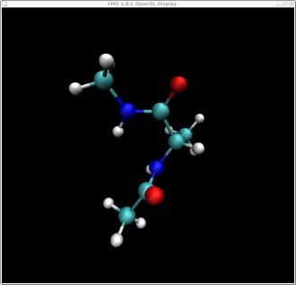
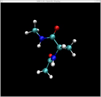
These two structures represent the two end points of the conformational change we want to find a pathway for. In this case rotation about the top O-C-C-N bond. These two structures represent the following two points on our potential energy surface. You can check this yourself in VMD.
|
|
Psi |
|
Phi |
These two points will be kept fixed during the simulation while 28 other replicated structures, that we will create in a minute, will be allowed to move according to the force they experience from the springs connecting them to each other and their own internal forces.
Here are the two pdb files for our two end point structures: struct1.pdb, struct2.pdb
I have pre-minimised these for you to ensure they are at minimum points on the energy surface.