


(Note: These tutorials are meant to provide
illustrative examples of how to use the AMBER software suite to carry out
simulations that can be run on a simple workstation in a reasonable period of
time. They do not necessarily provide the optimal choice of parameters or
methods for the particular application area.)
Copyright Ross Walker 20010
Nudged Elastic Band (NEB) simulations - SECTION 7
Formerly known as TUTORIAL A5: The Nudged Elastic Band Approach to Finding the Lowest Energy Pathway Between two States
By Christina Bergonzo, Carlos Simmerling & Ross Walker
7. Extracting the Final Pathway and Visualizing the Results
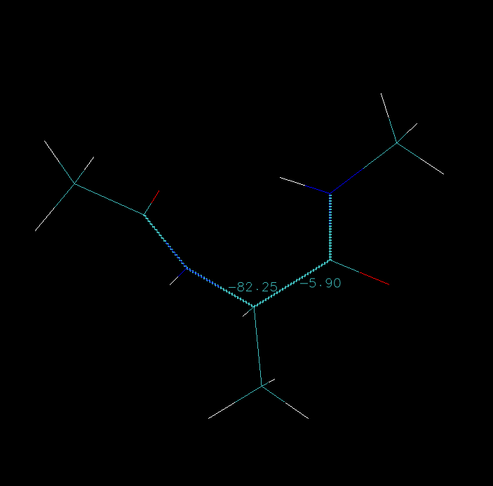
The final thing we shall do is to look at the actual pathway from a structural perspective and calculate the Phi-Psi angle for each image. We can begin by looking at the structures in the final restart files in VMD. We can combine these as we did in section 3.
#!/bin/bash rm ptraj.in top='../str1.prmtop' for ((i=0; i<=31; i++)); do ext=`printf "%03i" $i` echo "trajin ./neb.r.$ext" >> ptraj.in done echo "trajout ./cool.restarts.mdcrd" >> ptraj.in echo "go" >> ptraj.in $AMBERHOME/exe/ptraj $top ptraj.in |
Load the str1.prmtop file (select parm7 in vmd 1.8.3 or AMBER7 Parm in vmd 1.8.4 & later) and then into this molecule load the cool.restarts.mdcrd file (select AMBER coordinates). Under the Extensions -> Analysis -> RMSD Trajectory Tool, click "align" to align all the images. Now, you can step along the trajectory. Below is the measurement of the Phi and Psi angles as we step through this trajectory.
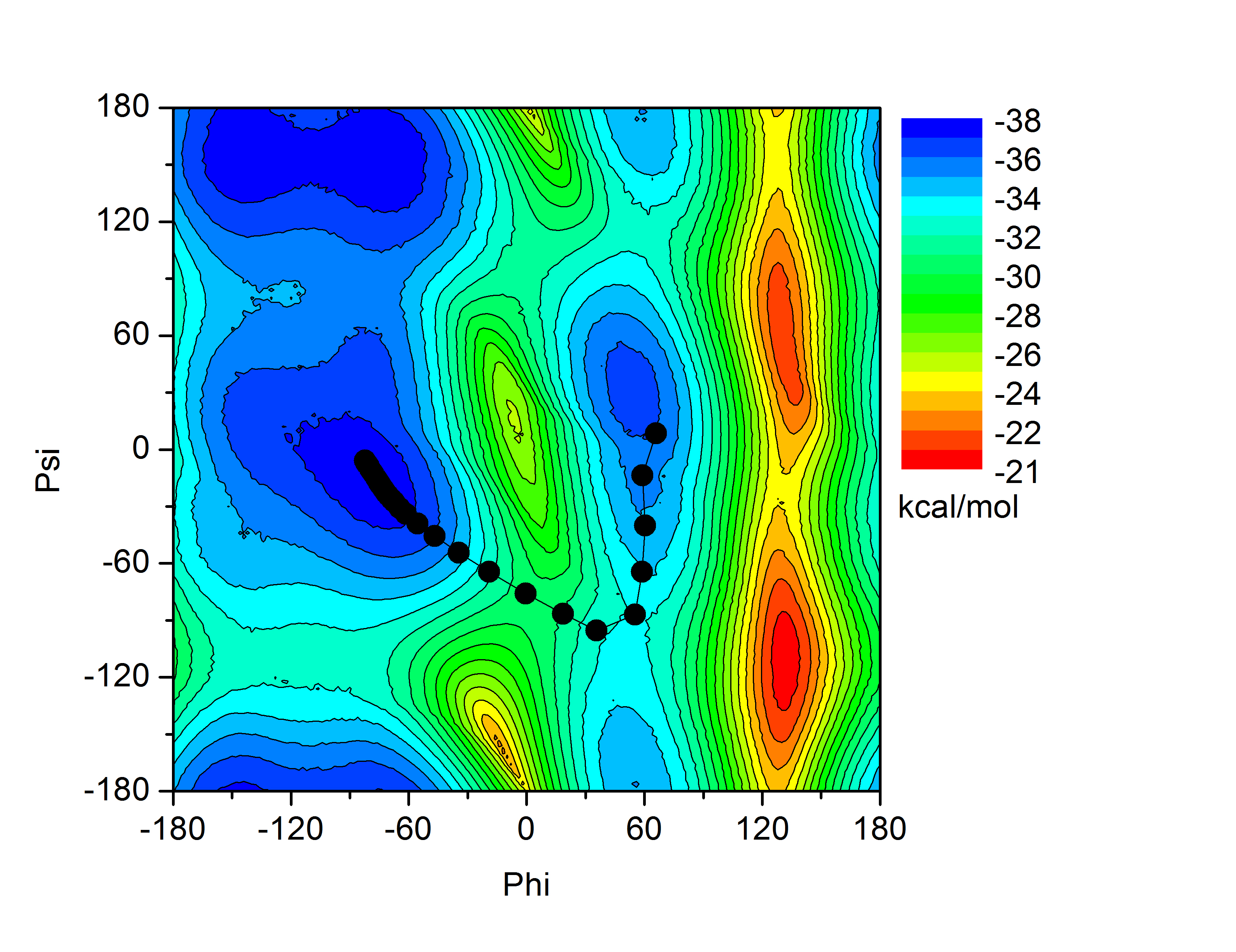
Below is each Phi-Psi value along the trajectory mapped onto the potential energy surface. We can see that the path taken is a minimum energy path for the transition between the two endpoint structures given.
(Note: These tutorials are meant to provide
illustrative examples of how to use the AMBER software suite to carry out
simulations that can be run on a simple workstation in a reasonable period of
time. They do not necessarily provide the optimal choice of parameters or
methods for the particular application area.)
Copyright Ross Walker 2010