SECTION 4: Thermodynamic integration calculations
FEW
facilitates the determination of relative binding free energies
by the thermodynamic integration (TI) approach for ligands binding
to the same receptor. The program provides the functionality for an
automated setup of the required thermodynamic integration (TI)
transformation simulations, and using the output of these simulations
it can compute relative ligand binding free energies with minimal user
intervention.
The basic principle of the TI approach for the determination of
relative binding free energies
is explained in Tutorial
A9.
Here exclusively the setup of TI calculations with FEW is shown. The
setup with FEW differs form the one presented in Tutorial
A9
mainly in that only one simulation is run (instead of three) for each
transformation,
i.e. one transformation simulation in water and one transformation
simulation in the solvated complex.
The simulations are prepared by FEW according to the 1-step, soft-core
approach (see
[11]
and page 355 of the Amber14 Manual),
which allows to change charges and vdW interactions in a single
simulation.
Note: Although the TI setup is performed here with pre-equilibrated structures, it is in principle possible to start TI calculations for any complex and ligand structures for which parameters have been prepared according to step 1A and for which solvated systems were generated, e.g. by step 1B. Please consult the FEW manual, if you plan to start TI simulations from non-equilibrated structures.
 |
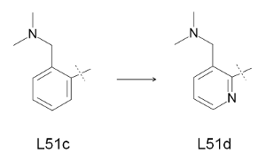
| Figure 6: Transformation investigated by the TI approach. |
For preparation of input structures and parameters and for setup of TI MD equilibration and production calculations one command file, called here TI_setup_L51c_d.in, is used. The different tasks (steps 1A - 2B below) are requested by setting flags in the respective parts of the command file to 1.
| TI_setup_L51c_d.in |
| @TIW ################################################################################ # Command file for TI simulation setup ################################################################################ # Location of input and output directories / file(s) # # lig_struct_path: Folder containing the ligand input file(s) # output_path: Basis directory in which all setup and analysis folders will # be generated. The directory must be identical with the # 'output_path' directory used for setup of the MD simulations. lig_struct_path /home/user/tutorial/structs output_path /home/user/tutorial ################################################################################ # Parameters required for TI simulation setup: # The following parameters have to be specified and need to be identical # in all subsequent runs for one system / TI-setup # # ti_simulation_setup: Request setup of TI simulation # charge_method: Charge method that shall be used, either "resp" or "am1" # lig_name_v0_struct: Name of start-ligand - Must be identical to the name of # the file in the "structs" folder used for generation of # parameter and library files with the common MD setup # functionality of FEW. # lig_name_v1_struct: Name of end-ligand - Must be identical to the name of # the file in the "structs" folder used for generation of # parameter and library files with the common MD setup # functionality of FEW. # lig_alias_v0: Alias that shall be used for the identification of the # start-ligand. The alias must consist of 3 characters. # lig_alias_v1: Alias that shall be used for the identification of the # end-ligand. The alias must consist of 3 characters. # softcore_mask_v0: Soft core atom mask for start-structure, specifying the # atoms of the start-structure (state V0) that shall be # regarded as soft core using the format # <lig_alias_v0>@<atom name list separated by comma> # softcore_mask_v1: Soft core atom mask for end-structure, specifying the # atoms of the end-structure (state V1) that shall be # regarded as soft core using the format # <lig_alias_v1>@<atom name list separated by comma> ti_simulation_setup 1 charge_method am1 lig_name_v0_struct L51c lig_name_v1_struct L51d lig_alias_v0 LFc lig_alias_v1 LFd softcore_mask_v0 LFc@C14,H1 softcore_mask_v1 LFd@N3 # ################################################################################ # 1) Parameters for preparation of coordinate and topology files of solvated # systems of start- and end-structures for TI simulations # # A) Generation of atom association list based on ligand mol2 files of # start and end structures # # prepare_match_list: Request creation of matching list prepare_match_list 1 # # B) Setup of coordinate and topology files # # It is required that RESTRT (coordinate) and topology files for the ligand and # complex of the start structure exist. These can be generated with the common # MD setup functionality of FEW. # # prepare_inpcrd_prmtop: Request setup of coordinate and topology files # lig_inpcrd_v0: Coordinate file (restart file) of ligand - start structure # com_inpcrd_v0: Coordinate file (restart file) of complex - start structure # lig_prmtop_v0: Topology of ligand - start structure # com_prmtop_v0: Topology of complex - start structure # match_list_file: Optional: File containing the atom association information # for the common part of start- and end-structures. Must only # be specified if step 1A was not successful and the list was # created manually. # chain_termini: Comma separated numbers of terminal residues of chains in # receptor structure. # create_sybyl_mol2: Request generation of mol2-files with sybyl atom types # for easy comparison of atom names of start- and end- # structures. Can facilitate checking and manual adjustment # of atom names in the end-structure, if automatic matching # is not successful. # additional_library: If an additional library file is required, e.g. for # non-standard residues present in the receptor structure, # this file must be specified here. # additional_frcmod: If additional parameters are needed, e.g. for describing # non-standard residues present in the receptor structure, # a parameter file should be provided here. # SSbond_file: File with disulfide bridge definitions # prepare_inpcrd_prmtop 1 lig_inpcrd_v0 /home/user/tutorial/MD_am1/L51c/lig/equi/md_nvt_red_06.restrt com_inpcrd_v0 /home/user/tutorial/MD_am1/L51c/com/equi/md_nvt_red_06.restrt lig_prmtop_v0 /home/user/tutorial/MD_am1/L51c/cryst/L51c_solv_lig.top com_prmtop_v0 /home/user/tutorial/MD_am1/L51c/cryst/L51c_solv_com.top match_list_file chain_termini 235 create_sybyl_mol2 1 additional_library /home/user/tutorial/input_info/CA.lib additional_frcmod SSbond_file /home/user/tutorial/input_info/disulfide_bridges.txt # 2) Setup scripts for TI MD # # General parameters # # no_shake: Set to "1", if no SHAKE shall be performed # ti_batch_path: Root path to be used in setup of batch files # ti_prod_template: Template script for TI production simulations no_shake 1 ti_batch_path /home/user/tutorial ti_prod_template /home/user/tutorial/input_info/MD_prod_noShake_TI.in # # A) Setup of scripts for equilibration # # ti_equil: Request generation of scripts for TI equilibration input # ti_equil_template: Template file for equilibration part of equilibration # phase of TI simulations. This equilibration part is # followed per default by a 1 ns free TI MD simulation # for complete equilibration of the system. # ti_equil_batch_template: Batch template file for equilibration phase of # TI simulations. # ti_equil_lambda: Values of lambda that shall be used in the calculation # in ascending order. Please specify only the decimal digits, # e.g. 1 for lambda 0.1, 05 for lambda 0.05. ti_equil 0 ti_equil_template /home/user/tutorial/input_info/equi_noShake_TI.in ti_equil_batch_template /home/user/tutorial/input_info/equi_TI.sge ti_equil_lambda 1,2,3,4,5,6,7,8,9 # # B) Setup scripts for production # # ATTENTION: This setup step can only be conducted if the equilibration # calculations have been completed. # # ti_production: Request generation of scripts for TI production input. # This setup step requires that the equilibration output is # present in the corresponding 'equi' folder. # ti_prod_lambda: Lambda steps for which the production shall be run; # separated by comma and in ascending order. Please specify # only the decimal digits, e.g. 1 for lambda 0.1. # total_ti_prod_time: Total production time requested (in ns) # ti_prod_batch_template: Batch template for TI production simulations # converge_check_script: Location of perl program to be used for convergence # checking after each production step. If the location # is not specified, it will be assumed that the program # can be found under the default location # at .../FEW/miscellaneous/convergenceCheck.pl # converge_check_method: Method that shall be used for convergence checking. # 1: Difference in standard error of dV/dL # 2: Precision of dV/dL according to student's # distribution # converge_error_limit: Error limit that shall be used as termination criterion # for the TI production simulations. # Defaults: 0.01 kcal/mol for method 1 # 0.2 kcal/mol for method 2 ti_production 0 ti_prod_lambda 1,2,3,4,5,6,7,8,9 total_ti_prod_time 1,1,1,1,1,1,1,1,1 ti_prod_batch_template /home/user/tutorial/input_info/prod_TI.sge converge_check_script converge_check_method 2 converge_error_limit 0.2 |
Definition
of global
parameters
The key terms of the very first part of the command file, where
Input/Output directories/file(s) are defined,
are identical to the ones of the Input/Output specification section of
the command files for MD simulation
setup discussed in section1.
In the TI simulation setup part it is specified that TI simulations
shall be prepared using AM1-BCC charges for the ligands.
Furthermore the names of the ligands, i.e. the names of the
MOL2-structure files, that shall be considered
for the transformation, lig_name_v0_struct
and lig_name_v1_struct
are
defined. The corresponding ligand aliases
lig_alias_v0
and lig_alias_v1
are
used as ID's and will appear e.g. in ligand residue names
and in file names. The softcore_mask's
define
the soft-core atoms, i.e. the atoms that shall be
changed, "appear" or "disappear", i.e. are decoupled, upon transfer of
ligand L51c into ligand L51d.
Step 1: Preparation of input coordinate and topology files
To request setup of coordinate and topology files for the TI simulations the flags ti_simulation_setup and prepare_inpcrd_prmtop need to be set to 1.
A: Before the actual input files are prepared, an atom association list is created in which the atoms that are structurally equivalent in both ligands are listed as pairs. The identification of equivalent atoms is necessary because all common atoms of the ligands need to be listed in the same order in the coordinate files later. Therefore a correct atom association list is essential for a successful setup of the simulations. Usually this step is conducted without any user intervention.
B:
When the atom association list has been created, the actual coordinate
and topology
files are generated. Files for the end state of the transformation,
that is L51d in the present case, are prepared based on coordinate
and topology files of the start state. Thus, coordinate files of the
solvated ligand L51c (lig_inpcrd_v0)
and of the solvated complex (com_inpcrd_v0)
need to be provided. The coordinate files are obtained here from the
final equilibration step of the MD simulations prepared (and run) in
section
1 of this tutorial. The
corresponding topology files used for the simulations are present in the
cryst
folders
of the simulation directories and are specified
in the command file under lig_prmtop_v0
and com_prmtop_v0.
As the protein
Factor Xa is not
a monomer, but consists of two chains, the end of the first chain is
defined under
chain_termini.
Other
specific receptor features can be handled via setting of additional_library, additional_frcmod, and SSbond_file, which
have been described before (see section
1).
Running
FEW:
After the
basic input/output path, i.e. the path
/home/user/tutorial
here,
has been changed to the
path where the tutorial files are stored on your local system, FEW can
be invoked by:
perl $FEW/FEW.pl TI /home/user/tutorial/cfiles/TI_setup_L51c_d.in
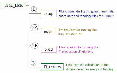
When you run FEW using the command-file given above with ti_simulation_setup and prepare_inpcrd_prmtop set to 1, a new folder called TI_am1 is created in the /home/user/tutorial directory. This folder contains a sub-folder named after the ligand names specified as lig_name_v0_struct and lig_name_v1_struct in the command file. In case of the names given in the command file above the folder will be named L51c_L51d. In this sub-folder all data associated with this specific transformation will be deposited (Figure 7). Currently only the setup folder exists, which contains the files generated during the setup of the coordinate and topology files.
 |
| Figure 7: Schematic depiction of the sub-structure of the transformation specific folder created upon setup of TI calculations with FEW. |
Step 2: Setup of TI MD simulations
A:
Equilibration
The preparation of files for the equilibration
phase of the TI MD simulations can be requested by setting ti_equil
to
1.
Simulations
are prepared without using the
Shake algorithm for constraining bonds involving hydrogen atoms.
(no_shake=1).
The
path defined as output_path
is
also used as Input/Output path for the
prepared batch scripts (ti_batch_path).
Input
files for the equilibration phase of the simulations
are created for the nine λ values 0.1, 0.2, 0.3, 0.4, 0.5,
0.6, 0.7, 0.8, and 0.9, using
the templates ti_equil_template and ti_prod_templ.
Currently
the pure equilibration step
conducted
according to the settings in ti_equi_templ
is
followed by a fixed 1 ns simulation employing the ti_prod_templ
to
ensure thorough equilibration.
The
batch template ti_equi_batch_template
needs
to be adapted for the local computing architecture
before usage by changing the top section of the script before the
Fix
variables
statement
as well as the section entitled
re-queuing.
When FEW is run by repeating the command from step 1 with the ti_equil flag switched on, a folder called equi is created in the transformation specific folder L51c_L51d (Figure 7). This folder contains two sub-folders, lig for the simulation of the free ligand in solution and com for the simulation of the solvated complex. Each of these folders contains beside the input files for the TI simulations a batch script called run.pbs for job submission via a queuing system. The TI equilibration jobs can be started by:
qsub /home/user/tutorial/TI_am1/L51c_L51d/equi/com/run.pbs
qsub /home/user/tutorial/TI_am1/L51c_L51d/equi/lig/run.pbs
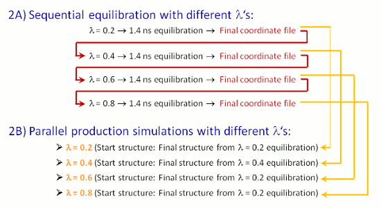
The equilibration steps for the different λ values will then be sequentially processed according to the scheme depicted in Figure 8.
 |
| Figure 8: Schematic depiction of the workflow during equilibration and production phase of the TI simulations. |
ATTENTION:
The setup of the production TI MD simulations
described below can only be started, when the equilibration simulations
have been completed for all λ
values that shall be considered in the production phase.
As running
the equilibration simulations can be time consuming, output
files with energies recorded during
the simulations are provided in the FEW tutorial folder. If you
want to use the provided MD output files
copy the file
link_TIequi_output.sh
into
your
basic input/output folder
cp $FEW/examples/tutorial/link_TIequi_output.sh /home/user/tutorial
and replace the path /home/src/FEW given in the third line by the path under which FEW is installed under your local system. Then execute the script.
/home/user/tutorial/link_TIequi_output.sh
Then exit the shell and check that softlinks have been created in the com and lig folders under /home/user/tutorial/TI_am1/L51c_L51d/equi.
B:
Production
The preparation of input files for the production part of the
transformation simulations is invoked by setting ti_production
to
1.
Setup
of simulations is requested
here for all nine λ steps
for which equilibration
calculations have been performed. It would also be possible to request
production setup only for a part of those λ's for
which equilibrations have been run. However, it is essential, that the
size
of Δλ, i.e. the λ step size, is
equivalent
for all Δλ's. Consequently, to run
simulations only for the λ values 0.2, 0.4, 0,6, and 0.8
would also have been
possible.
TI
production simulations are started based on the final coordinate files
from the equilibration. A
precision
better than 0.2 kcal/mol (according to student's distribution
at a confidence level of 95%) will be used as termination criterion for
the simulations.
If this criterion is not reached the simulations at all λ
values will be terminated after total_ti_prod_tim=1 ns.
The
batch template file ti_prod_batch_template
needs
to be adapted in the same way as the ti_equil_batch_template
file
above and serves then as template file for the setup of batch files for
the submission of TI production jobs.
Running
FEW:
When the computing environment specific changes have been made,
setup of the TI production
simulations by FEW can be invoked using a command file
in which
ti_production
is
switched on.
perl $FEW/FEW.pl TI /home/user/tutorial/cfiles/TI_setup_L51c_d.in
The setup
starts with a
check of the equilibration according to the
reverse cumulative averaging procedure
[12,
13],
to
ensure that the system is equilibrated and can be used for TI
production.
After the checking routine has been completed, you are notified whether
the equilibration check was
successful. In the present case the equilibration check is passed for all λ's of both ligand and complex system. It can happen that the overall equilibration check is passed, but
that the equilibration check failed for individual λ's. In this case the respective equilibrations should be
further analyzed to completely
rule out the presence of any problems during equilibration that could
lower the accuracy of the
binding free energy prediction later. A plot of the dV/dλ
values
versus
the simulation time
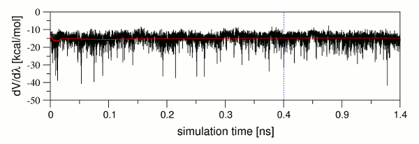
can be valuable for the identification of such problems. Figure 9 shows
such a plot of dV/dλ values
extracted form the output files and
their cummulative average (red line) plotted versus the simulation
time. It is obvious that although
the dV/dλ values fluctuate
considerably, the cummulative average is relatively constant. This
indicates that the
system is on average already in an equilibrated state, and that only
longer sampling will be needed
to reach the same precision as at the other λ
values. As a
control of the precision level
in the production runs is ensured via the implemented convergence
check, the final structures of the
equilibration can be used as input structures for the
production in such a case.
 |
| Figure 9: Plot of dV/dλ (black) and its cummulative average (red) versus the simulation time. The point in the simulation where the pure equilibration part ends and the 1 ns production part of the equilibration phase starts is indicated by a blue dashed line. |
The files for the TI production simulations are deposited in a folder called prod. This folder contains, as the equi folder described above, two sub-folders, lig and com, for the simulations of the ligand in solution and of the solvated complex, respectively. The production simulations can be started by submission of the batch scripts, e.g.:
/home/user/tutorial/TI_am1/L51c_L51d/qsub_prod.sh
Note: Since carrying out TI simulations for two systems at nine λ values is computationally expensive, the output files of the simulations containing the energy values are provided with FEW. If you wish to use these files, please copy the script copy_TIprod_output.sh into the tutorial folder
cp $FEW/examples/tutorial/copy_TIprod_output.sh /home/user/tutorial
and change the path /home/src/FEW to the directory where FEW is installed on your local system. Then execute the script.
/home/user/tutorial/copy_TIprod_output.sh
After completion of the script, exit the shell and check that the output files from TI production were copied into the lig and com folders under /home/user/tutorial/TI_am1/L51c_L51d/prod.
Step 3: Calculation of the relative binding free energy
The difference in binding free energy between L51c and L51d ΔΔGbinding can be computed with FEW in an automated fashion based on the output from TI production simulations. The command file TI_setup3_L51c_d.in contains the parameters required for this task.| TI_setup3_L51c_d.in |
| @TIW ################################################################################ # Command file for calculating the difference in binding free energy # between start and end ligand based on TI simulations. ################################################################################ # Location of input and output directories / file(s) # # lig_struct_path: Folder containing the ligand input file(s) # output_path: Basis directory in which all setup and analysis folders will # be generated. The directory must be identical with the # 'output_path' directory used for setup of the MD simulations. lig_struct_path /home/user/tutorial/structs output_path /home/user/tutorial ################################################################################ # Parameters required for TI analysis: # # ti_ddG: Request calculation of difference in binding free energy. # charge_method: Charge method that shall be used, either "resp" or "am1" # lig_name_v0_struct: Name of start-ligand - Must be identical to the name of # the file in the "structs" folder used for generation of # parameter and library files with the common MD setup # functionality of FEW. # lig_name_v1_struct: Name of end-ligand - Must be identical to the name of # the file in the "structs" folder used for generation of # parameter and library files with the common MD setup # functionality of FEW. # lig_alias_v0: Alias that shall be used for the identification of the # start-ligand. The alias must consist of 3 characters. # lig_alias_v1: Alias that shall be used for the identification of the # end-ligand. The alias must consist of 3 characters. # dVdL_calc_source: Specification of files considered in computation of ddG: # 0: All files available for ligand and complex are considered # X-Y: Where X is the number of the first and Y is the number # of the last production file that shall be taken into account. # If Y=0 all files from X on will be considered. # ddG_calc_method: Method to be used for the calculation of dG: # 1: Conventional numerical integration with interpolation # to lambda=0 and lambda=1. # 2: Numerical integration without interpolation # ti_ddG 1 charge_method am1 lig_name_v0_struct L51c lig_name_v1_struct L51d lig_alias_v0 LFc lig_alias_v1 LFd dVdL_calc_source 0 ddG_calc_method 1 |
The Input/Output specification section of this command-file is already familiar. Also the ligand specific definitions in the TI analysis part of the file were explained above. The only important new parameters are dVdL_calc_source and ddG_calc_method. The first of these parameters determines, which files from TI production will be regarded for the calculation of ΔΔGbinding. Here we use all files created during TI production. It would, however, also be possible to regard e.g. only dV/dλ values from files recorded after a certain simulation time.
As calculation method the conventional calculation according to the trapezoidal rule with linear extrapolation to the end states λ=0 and λ=1 is used here. For the alternative option please consult the FEW manual and [13].
After FEW has be executed with the TI_setup3_L51c_d.in command file, a new folder called TI_results can be found in the transformation specific directory (Figure 7). This folder contains text-files listing all dV/dλ values regarded in the calculation of ΔΔGbinding, a log-file, and a file called TI_dG.out in which the final results are provided.
The computed difference in free energy of binding between L51c and L51d is 2.00 kcal/mol. Please consider this as a very rough estimate of the binding free energy, since within the short simulation time of 1 ns the dV/dλ values did not reach the desired error limit for all λ's. Especially the errors for the λ's 0.8 and 0.9 in the complex state are still high. One should also keep in mind that the transformation applied here was very small, so that the production simulations could converge relatively fast, for other transformations much longer simulations might be required to obtain good predictions.
SECTION 1: Setup of MD simulations
SECTION 2: MM-PB(GB)SA calculations
Copyright: Nadine Homeyer 2013


